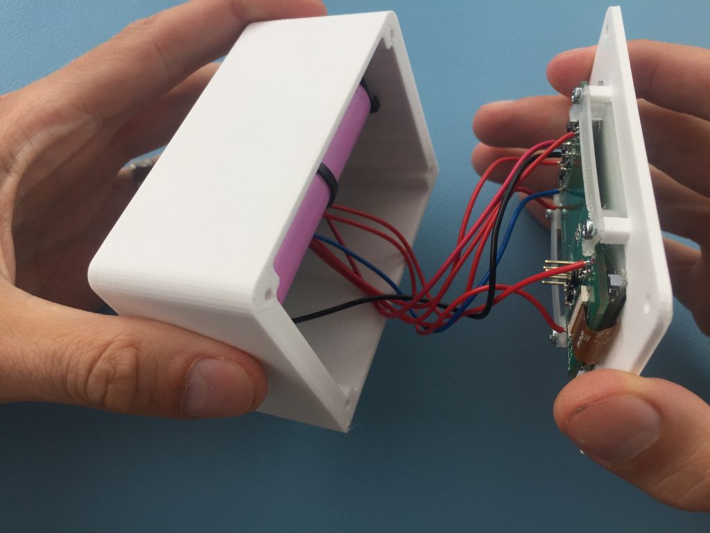
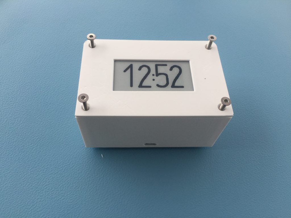
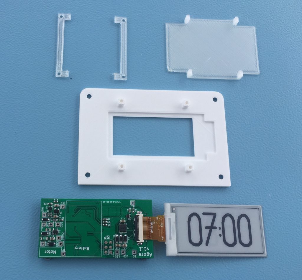
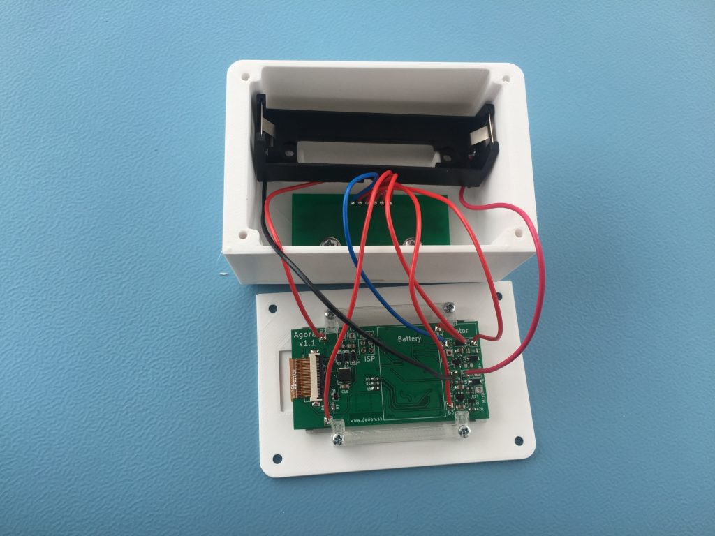
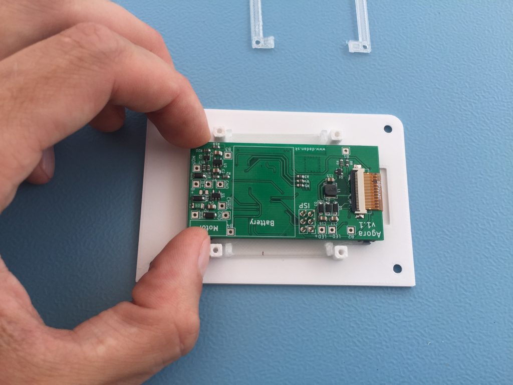
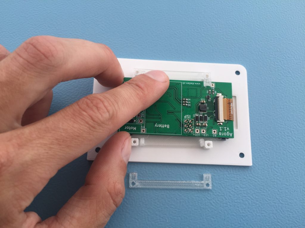
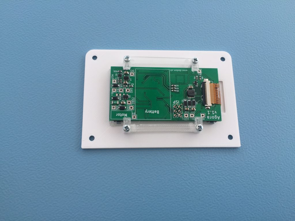
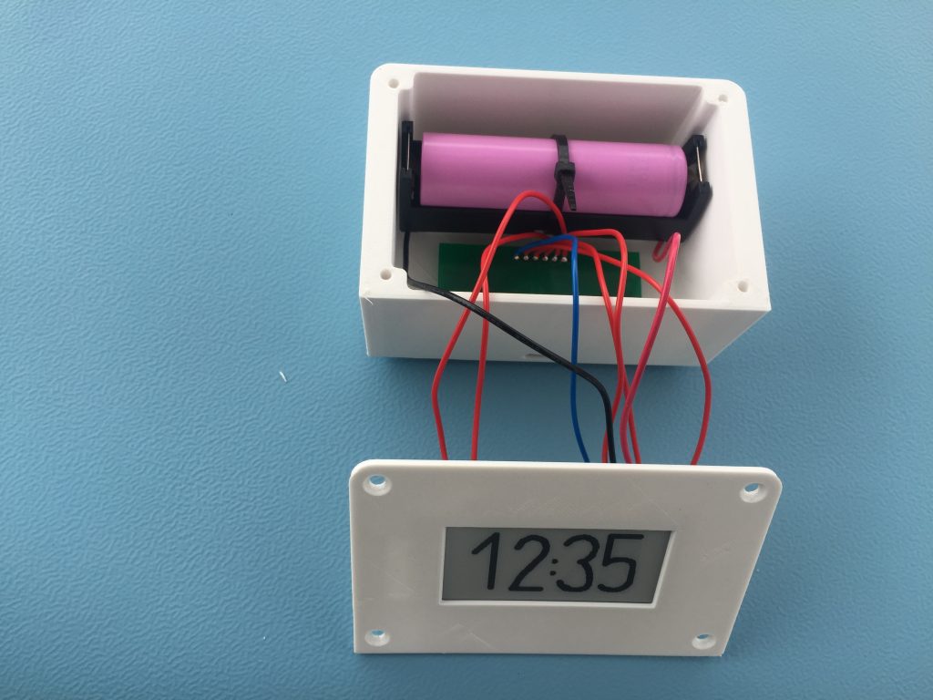
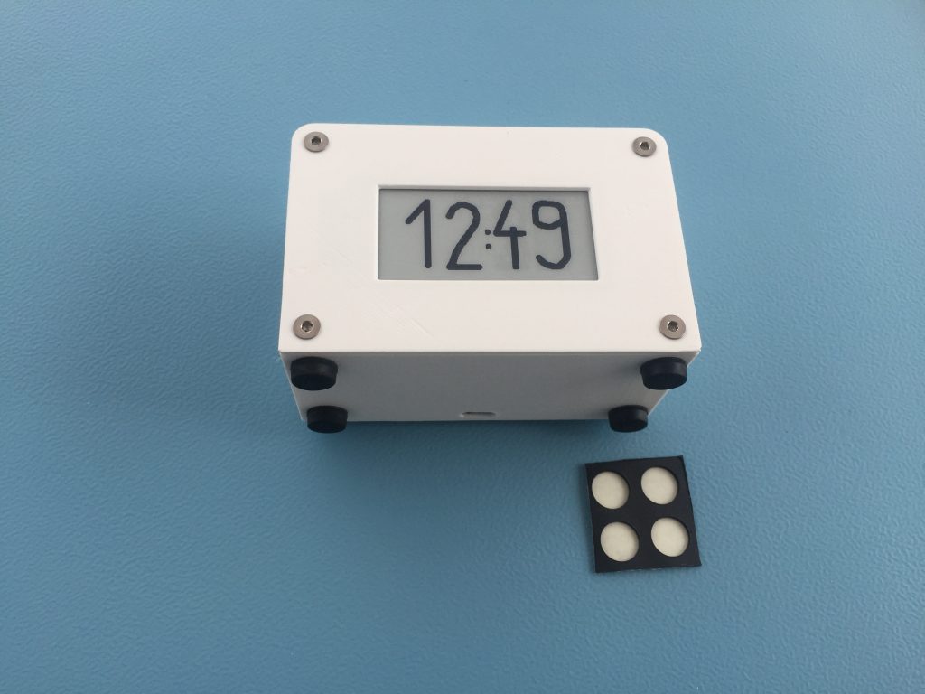
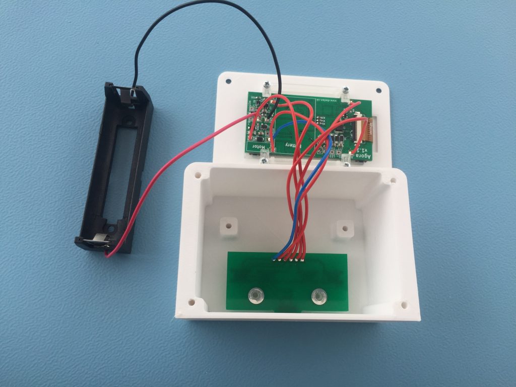
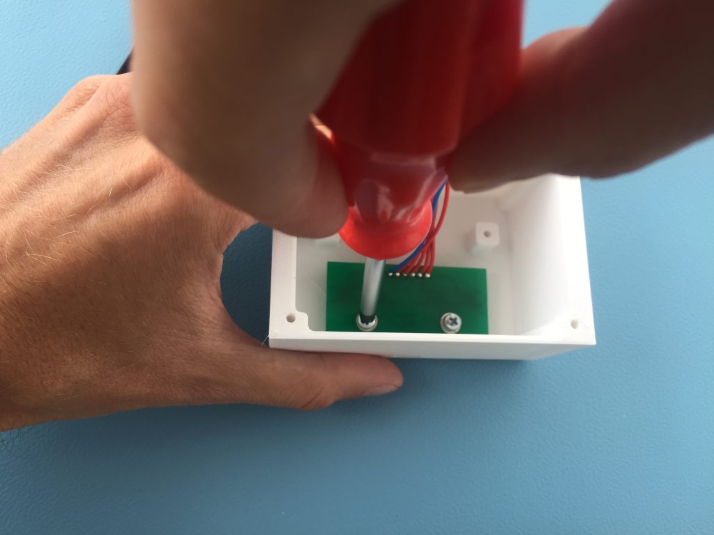
Agora clock assembly guide

Front panel

Let’s start with the front panel
Put the display into the hollow
Insert the display holder and hold it with your finger. Display have to stay in the hollow, otherwise it can be broken during the assembly
Bend the display flex cable and put the PCB on the display holder
Attach the PCB holder on one side and gently fasten the M2x4 screws
Put the screw also on the other side. Before fastening the screws check if the display is still in the hollow. Do not over tight the screws

The clock body

First solder wires into the button PCB. Recommended length is 130 mm
Solder the wires to the main PCB

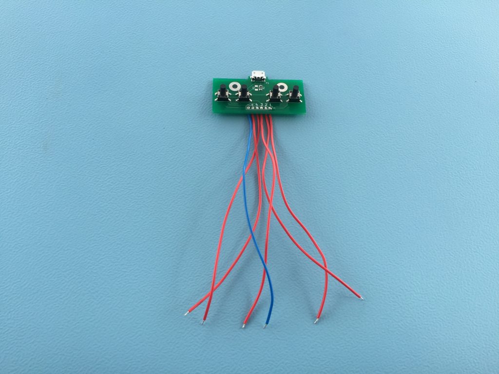
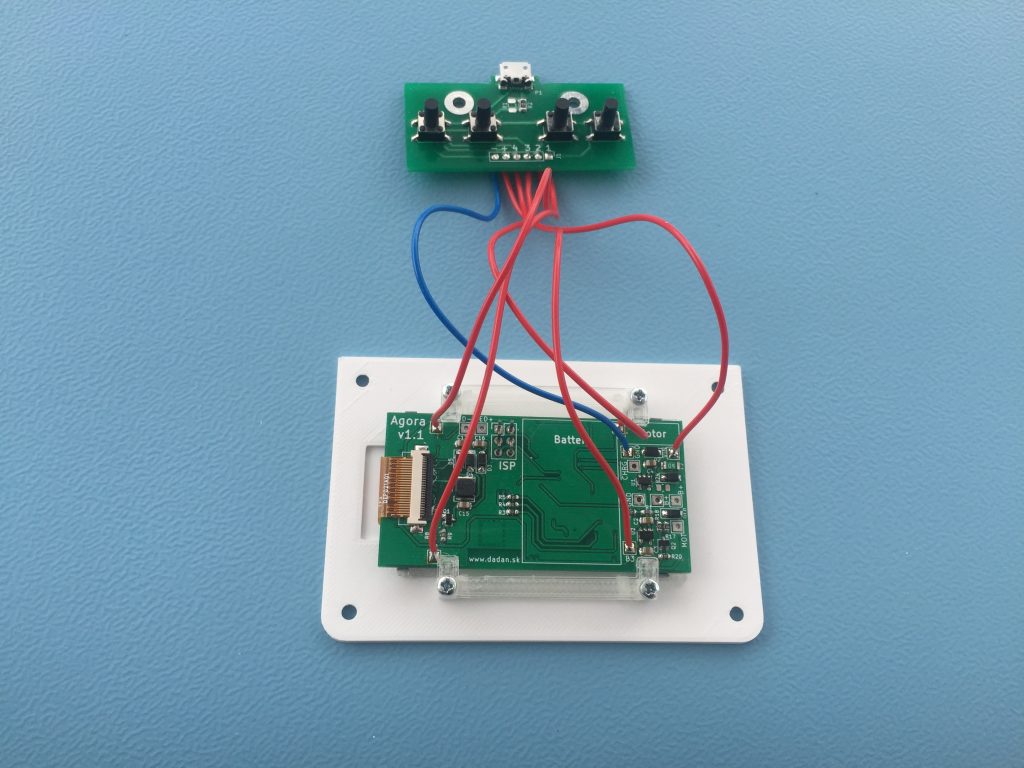
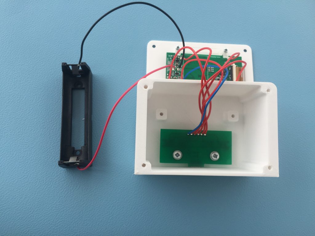
Connections (Button PCB -> Main PCB):

  • + to VIN
  • – to GND
  • 1 to B1
  • 2 to B2
  • 3 to B3
  • 4 to B4
Solder the battery holder.
Insert the button PCB into the clock body. Sometimes it’s needed to do little adjustments with modelling knife if the PCB won’t fit into the body.
Fasten with the M3x4 screws
Button PCB secured in the body
Install the battery holder. Use M3x4 screws. The wires should go under the holder.
Put a battery into the holder and prepare a 100 mm zip-tie.

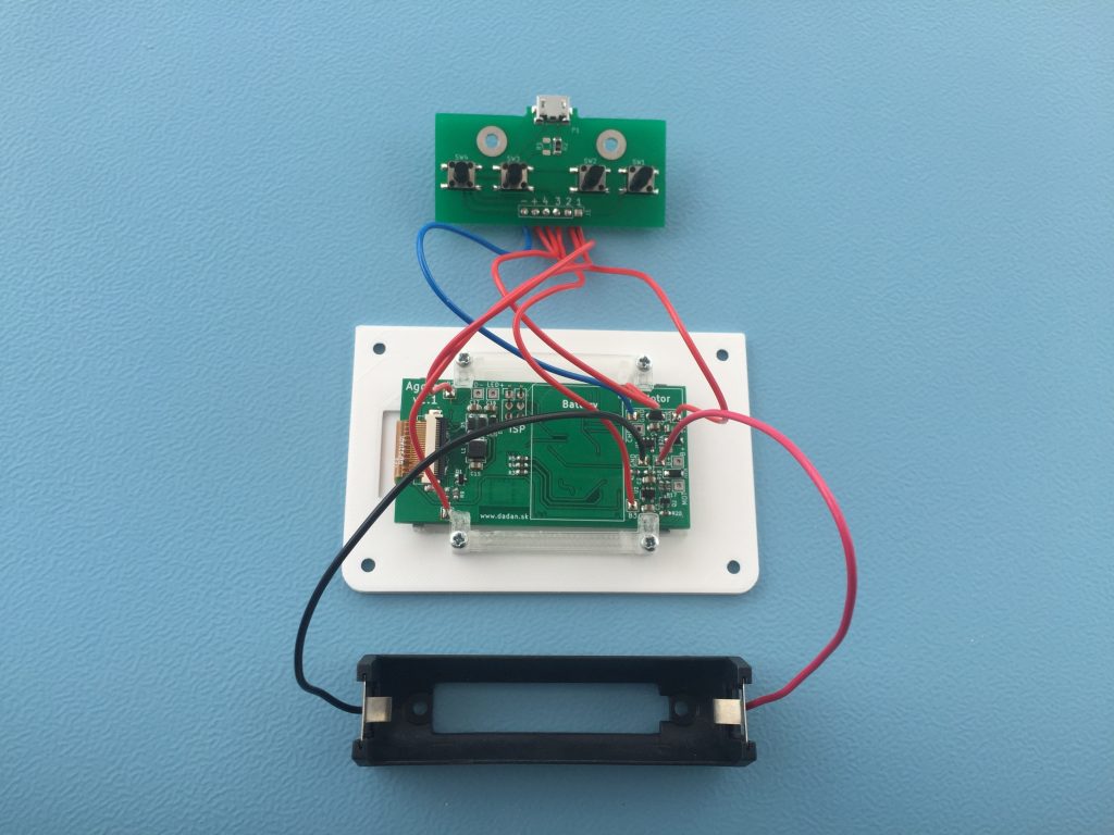
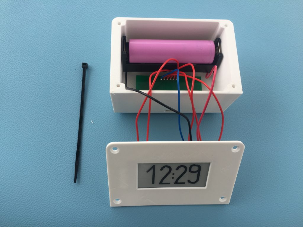
Warning: Pay attention to the battery polarity! Red wire goes to the positive terminal (+). It is the one with smaller metal cap. Electronics will be damaged if the battery is connected incorrectly !!!

Install the zip-tie. It holds the battery if the clock is shaken or it hit the floor. Cut the excessive zip-tie end with pliers.
Twist the wires – one turn is enough. It helps with the assembly. Then put the front panel and the body together.
Insert and tighten the M3x14 hex screws.
Install the rubber self-adhesive legs.
And it’s done