
The heart of the project. I have chosen Atmega328p MCU which is not very powerful, but I wanted to keep things simple as possible and it’s very well known between hobbyists. Although the firmware itself is not compatible with Arduino, the hardware is. So it’s possible to upload Arduino sketches directly into Agora PCB. On the board there is ISP connector used to upload firmware to the MCU. Either with dedicated Atmel programmer or with an Arduino board with special sketch that acts as an ISP programmer.
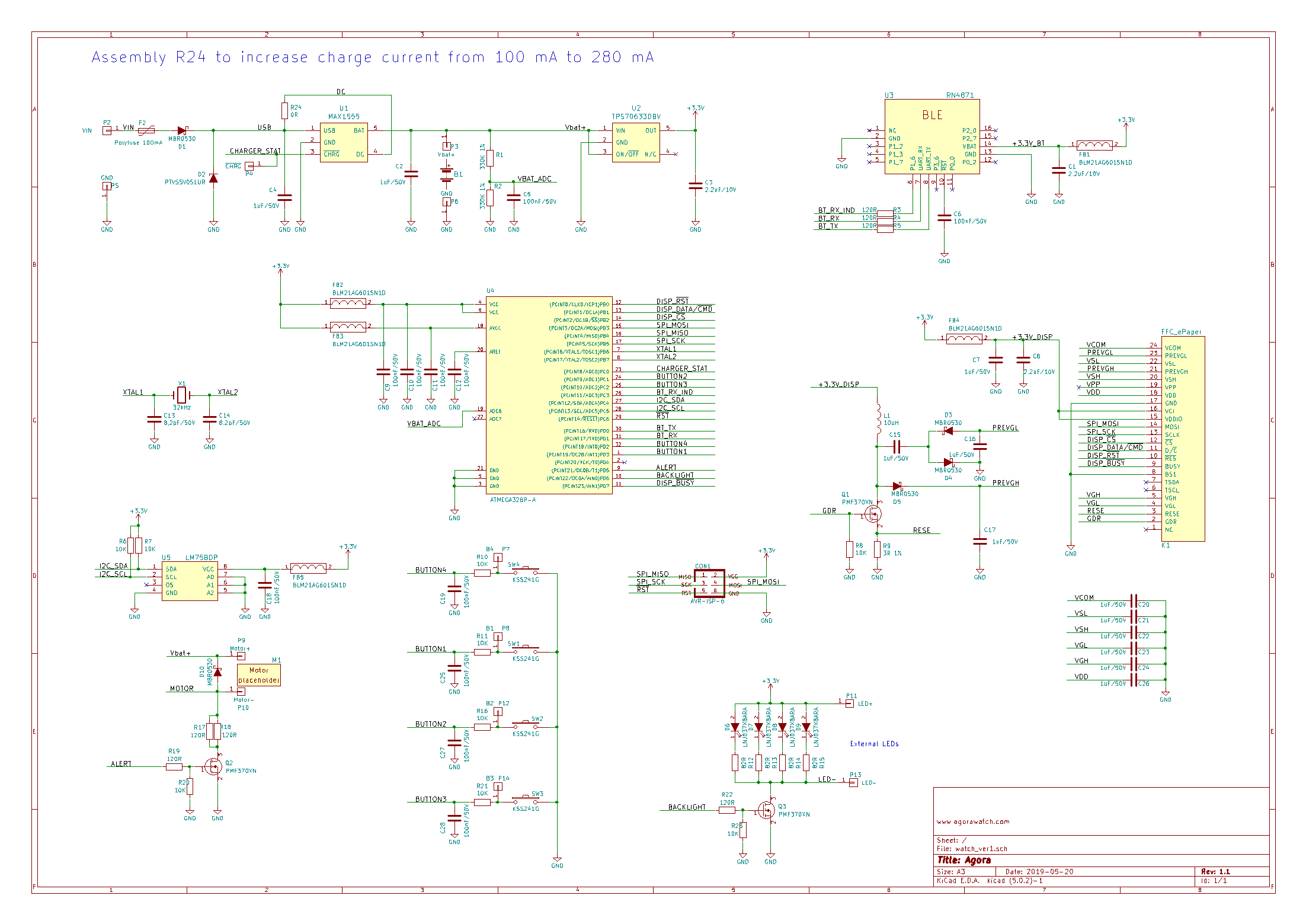
The schematic itself is also simple. It consists of this blocks:
- Power supply with battery charger
- MCU with crystal
- e-paper connector and power supply
- buttons
- LEDs
- vibration motor/buzzer output
- temperature sensor
- ISP connector
- bluetooth BLE module (currently not used)
(I will add the description of the blocks in a near future)
PCB
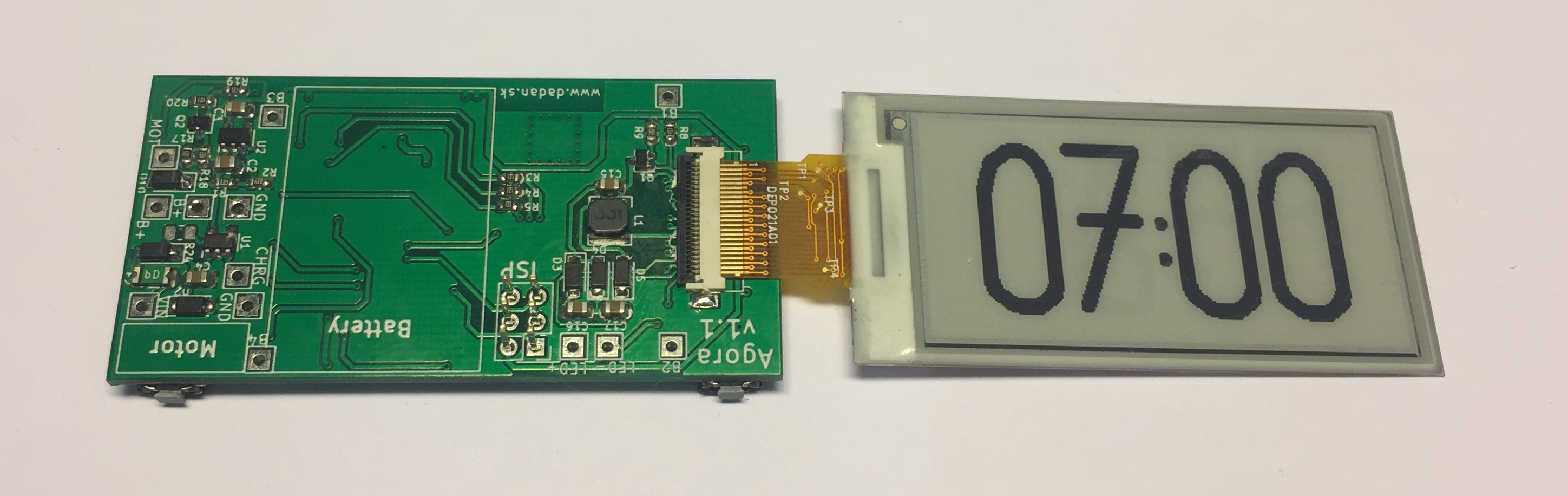
There are more ways how the assembled PCB can be used. Either it can be used to build Agora clock or Agora watch or you can be more creative and make something unique. Like a fridge thermometer or a cycle-computer. Here are some basics how to wire the PCB.
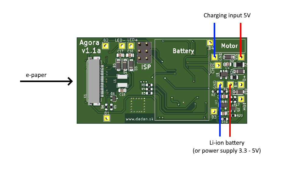
For minimal functionality just connect the e-paper display and Li-ion battery or regulated power supply to B+ and GND pins. The voltage should be between 3.3V and 5V. When the Li-ion (or Li-pol) accumulator is connected, it can be charged using VIN and GND pins. The charging current is limited to 100 mA.
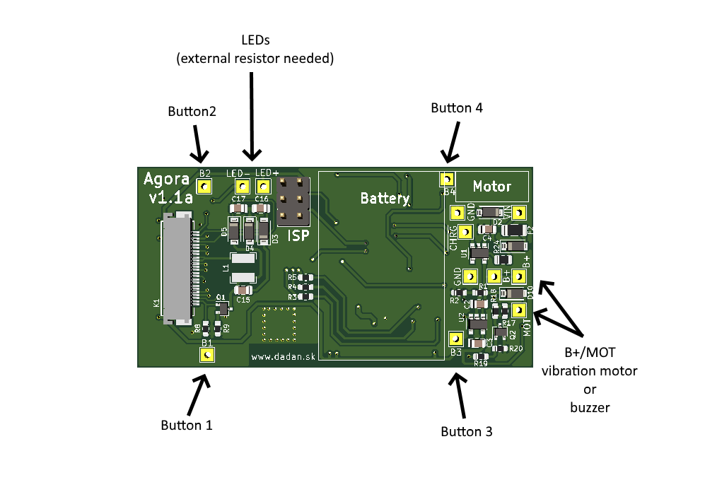
If you need to connect external buttons you can use the B1-4 pins (connect the button between the B1-4 pin and GND). You can also use LED+ and LED- for external LEDs, but pay attention – you need to add current limiting resistor.
There is also a pair of pins for vibration motor/buzzer. This output has a build-in current limiting resistor. The LED and MOT output are open-drain type so they can be used also for other purposes.